


Status sensor with bracket
horizontal foot
stainless steel
bright
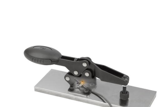
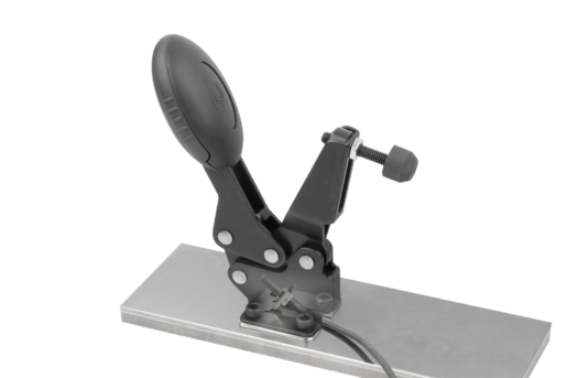
- Monitor toggle clamp actuated status
- Sensor
- Process control
- Attachment for existing toggle clamps
- Individually adjustable
£84.54
plus sales tax
Added to your shopping cart
Designation
Status sensor with bracket
Form
H
Size
3
Version 1
horizontal foot
Version 2
normally open
Body material
stainless steel
Component material
stainless steel
Body surface finish
bright
Component surface finish
bright
G1=THREAD
M08X1
G=Thread
M05X0,5
H=Height
20,1
L=Length
27
M=Spindle toggle clamp
M06X35
P=Cable length
300
SW=Key width
7
A
26
A1
39
A2
6,5
B
28
B1
39
B3
8
B4
23
B5
2
D
5,5
Form definition
for horizontal toggle clamps
L1
13,8
L2
39
PL FEATUREgrip
TRUE
Packaging unit
1
Description
Product description
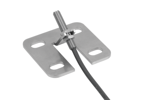
Status sensors with brackets are used to monitor the actuated status of toggle clamps.
The sensor detects whether the toggle clamp is open or closed and enables this status information to be processed electronically.
The sensor is attached to the toggle clamp via the bracket.
The sensor detects whether the toggle clamp is open or closed and enables this status information to be processed electronically.
The sensor is attached to the toggle clamp via the bracket.
Material
Stainless steel
Version
Bright.
Note
The status sensor and brackets are supplied unassembled.
Technical Data
Inductive sensor:
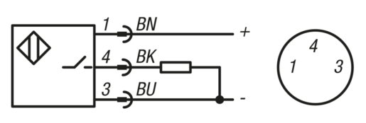
Output circuit: PNP NO
Operating voltage: 10 - 30 V DC
Operating current: 100 mA
Contact gap: 0.8 mm
Switch frequency: 5000 Hz
Short-circuit proof: yes
Reverse polarity protection: yes
Rating: IP 67
Connection type: 0.3 m cable, PUR with plug
Temperature range: -25 °C - +70 °C
Approvals: CE, c UL us, EAC
Assembly
The status sensor is fastened to the bracket with the nuts and set to dimension L1.
The bracket is attached with the toggle clamp screws through holes between the foot and the mounting surface.
The switch point fine-tuning is carried out once the toggle clamp is mounted.
The detailed procedure is described in the assembly instructions.
The bracket is attached with the toggle clamp screws through holes between the foot and the mounting surface.
The switch point fine-tuning is carried out once the toggle clamp is mounted.
The detailed procedure is described in the assembly instructions.
Safety
Status sensors are not suitable for protecting people.
Drawing reference
1) LED-indicator
BN = brown
BK = black
BU = blue
BN = brown
BK = black
BU = blue
Accessory
05900
10451
80140
10451
80140
Important note on downloading CAD models
In order to download our CAD models, you must log in first. If you have not created an account yet, please register under "My Account" (right side of the screen) and follow the instructions.
Other customers also bought


