{"product":{"productId":"agid.22278","price":298.29,"name":"PNEUMATIC CLAMP W. VERT. CYL.ATTACHMENT SIZE:2, L6=93, B=54,5, F1=1STEEL, COMP:STAINLESS STEEL"},"currency":"GBP"}
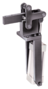
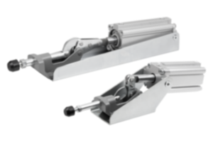
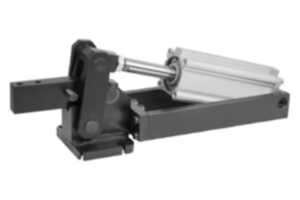
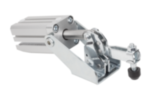
Pneumatic clamp
with vertical cylinder attachment
steel
- Pneumatic clamps are used as assembly and workholding fixtures
- Application sectors: machine construction, metal processing, woodworking, plastics industry
- Double action
- Automatable
Sales unit
£298.29
plus sales tax
Registered customers are offered live availability of the item after logging in to the website. Please log in or register to see the live availability or request a quotation.
Added to your shopping cart
Item
Pneumatic clamp
Size
2
Version 1
with vertical cylinder attachment
Main
material
steel
Component
material
stainless steel
B=Width
54,5
L6=Length
93
B1
6
B2
27
D
5,6
D1
12
F1
kN
1
F2
kN
1,2
F3
kN
0,7
F4
kN
1
H
65
H1
94
H2
15,8
H3
12
H4
12,5
H5
12,5
H6
38,4 - 45,0
H7
143,5
H8
67,5
L1
56,5
L2
12,5
L3
15,3
L4
25
L5
6,5
R
M5
VL
0,26
suitable
thrust screws
M6x35
α
90°
Description
Material
Levers steel plate.
Hinge pins stainless steel.
Hinge pins stainless steel.
Version
Lever parts electro zinc-plated.
Pneumatic cylinder, double-acting.
With magnetic piston for end position feedback.
Clamp trivalent passivated.
Complete with tempered, trivalent passivated thrust screw with protective cap.
Pneumatic cylinder, double-acting.
With magnetic piston for end position feedback.
Clamp trivalent passivated.
Complete with tempered, trivalent passivated thrust screw with protective cap.
Note
Pneumatic clamps have the following advantages compared to hand clamps:
The operator is relieved of frequent clamping.
Several clamps can be activated at the same time and can be closed in a specific sequence.
Single or multiple clamps can be activated from varying positions by machine control or hand control.
Because of the toggle system:
– the clamp remains closed if the air supply fails.
– the air consumption is low due to the large end ratio.
– pivoting the clamping arm achieves a large opening travel.
– optimum force and movement ratios are achieved.
VL = air consumption per complete cycle in dm³ at 6 bar.
Control
The schematic diagram for the simplest control of one or several pneumatic clamps is shown here. When constructing complete switching systems consult a well known manufacturer of pneumatic valves who can also supply all the required connectors and fittings.
Attention
The forces F1 and F2 specified in the table are holding forces.
F3 and F4 are clamping forces.
F3 and F4 are clamping forces.
Selection criteria
To select the correct size of pneumatic clamps, the possible clamping force at 6 bar (any compressed media are permissible, maximum pressure 10 bar) is specified besides the retaining force. F3 is the possible clamping force that the clamp exerts on the end of the clamping arm, F4 the force it exerts on the fulcrum side.
Important note on downloading CAD models
In order to download our CAD models, you must log in first. If you have not created an account yet, please register under "My Account" (right side of the screen) and follow the instructions.


