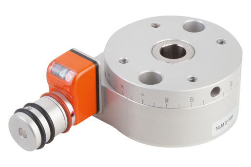


Rotary Positioning Table
aluminium
- 360° travel with no end plate
- Self-locking and hardened spindle
- Scale indicates 10° steps
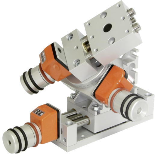
- Modular design offers simple combination options
- Maintenance-free
£393.67
plus sales tax
Added to your shopping cart
Designation
Rotary Positioning Table
Version 2
with position indicator
Body material
aluminium
Component material
steel
D2=Diameter
54
D3=Hole spacing
36
D
26
D1
23
D2
54
D3
36
D4
10
D5
M04X6
D6
4
F1 (N)
500
F2 (N)
500
F3 (N)
200
H
30
H1
14
H2
9
H3
6
L
80
L1
17
L2
29
L3
36
M1 Nm
3
Description
Material
Body and rotary table Al alloy, anodised.
Spindle steel, case-hardened.
Spindle bearing maintenance-free.
Position indicator plastic.
Spindle steel, case-hardened.
Spindle bearing maintenance-free.
Position indicator plastic.
Version
Radial play of rotation axis < 0.015 mm.
Axial play of rotation axis < 0.02 mm.
Repeat accuracy < 0.05°.
Spindle self-locking.
Axial play of rotation axis < 0.02 mm.
Repeat accuracy < 0.05°.
Spindle self-locking.
Note
360° adjustment, no end stop.
The position indicator reads in increments of 0.1° increasing clockwise from 0.0° to 9.9° while the rotary table rotates counter-clockwise. A scale on the circumference of the rotary stage is marked every 10°.
The position indicator can be re-mounted in any of 4 positions by removing the grip and loosening the two screws.
Transmission ratio:
21161-08 = 50:1
21161-12 = 55:1
The rotary stage can be easily combined with other modules of the same size.
Drawing reference
Assembly position of position indicator:
a) top (standard)
b) right
c) bottom
d) left
All counterbores to DIN 74-Bm (D6)
a) top (standard)
b) right
c) bottom
d) left
All counterbores to DIN 74-Bm (D6)
Important note on downloading CAD models
In order to download our CAD models, you must log in first. If you have not created an account yet, please register under "My Account" (right side of the screen) and follow the instructions.
Other customers also bought


